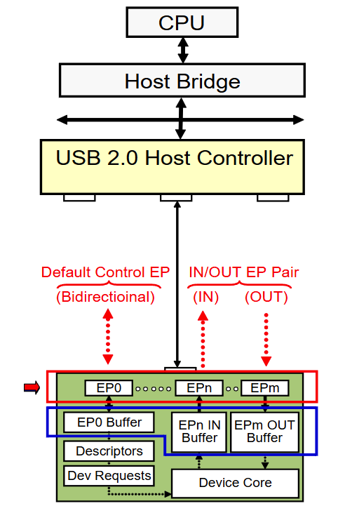
Each USB device contains one or more endpoints, which are the fundamental communication channels used to exchange data with the host. An endpoint is identified by its number, direction, and transfer type — together these form the basis of the device's programming interface.
Maximum Number of Endpoints
A USB device can support up to 32 logical endpoints:
| Component | Count |
|---|---|
| Endpoint 0 IN + OUT (bidirectional) | 2 (counted as 1 control pipe) |
| Endpoints 1–15 IN | up to 15 |
| Endpoints 1–15 OUT | up to 15 |
| Total logical endpoints | 32 |
- Endpoint 0 (EP0) is mandatory for every device — see Control Endpoints.
- The remaining endpoints are optional and depend on the device's class and function.
Endpoint 0 is the only endpoint that is bidirectional. All other endpoints are unidirectional — an IN and OUT endpoint with the same number are two completely independent endpoints.
Endpoint Addressing
Each endpoint is uniquely identified by a combination of:
| Field | Bits | Description |
|---|---|---|
| Endpoint Number | 3:0 | 0–15 |
| Direction | 7 | 0 = OUT, 1 = IN |
This is encoded in the bEndpointAddress field of the Endpoint Descriptor.
Example
bEndpointAddress |
Meaning |
|---|---|
0x01 |
Endpoint 1 OUT |
0x81 |
Endpoint 1 IN |
0x02 |
Endpoint 2 OUT |
0x83 |
Endpoint 3 IN |
Endpoint Direction
IN Endpoint
- Sends data from the device to the host
- The device loads data into its IN endpoint buffer
- The host retrieves the data by issuing an IN token
OUT Endpoint
- Receives data from the host to the device
- The host sends data with an OUT token
- The device stores the data in its OUT endpoint buffer
Bidirectional Communication
To support two-way data transfer, a device implements a matched pair:
Host ── OUT ──► Endpoint 1 OUT buffer (device receives)
Host ◄── IN ── Endpoint 1 IN buffer  (device sends)
These are separate endpoints with separate buffers, even though they share endpoint number 1.
Endpoint Buffers
Each endpoint must include a buffer capable of storing at least one full-size USB packet.
The required buffer size is defined by the wMaxPacketSize field in the Endpoint Descriptor.
Maximum Packet Sizes by Speed and Transfer Type
| Transfer Type | Low-Speed | Full-Speed | High-Speed |
|---|---|---|---|
| Control | 8 | 8, 16, 32, or 64 | 64 |
| Bulk | — | 8, 16, 32, or 64 | 512 |
| Interrupt | 1–8 | 1–64 | 1–1024 |
| Isochronous | — | 1–1023 | 1–1024 |
SuperSpeed endpoints can carry up to 1024 bytes per packet and support burst mode (up to 16 packets) — see SS Endpoint Companion Descriptor.
Double Buffering
Some device implementations use double buffering (ping-pong buffers):
- While the host reads from one buffer, the device fills the other
- Improves throughput by overlapping data transfer and processing
- Common in high-throughput endpoints (bulk, isochronous)
Why Buffers Are Needed
USB is a host-scheduled bus — the device cannot initiate transfers on its own. Buffers bridge the timing gap:
- OUT direction: The host may send data before the device firmware is ready to process it — the buffer holds incoming data
- IN direction: The device firmware prepares data in advance — the buffer holds it until the host polls
- Speed mismatch: The USB bus operates at fixed frame intervals (1 ms for FS, 125 µs for HS) while device processing time varies
Without buffers, data would be lost whenever the bus and device firmware are not perfectly synchronized.
Endpoints as the Device Programming Interface
The complete set of endpoints defines how software communicates with the device:
┌──────────────────────────────────────────────┐
│              Host Software                   │
│  ┌──────┐  ┌──────┐  ┌──────┐  ┌──────┐      │
│  │Pipe 0│  │Pipe 1│  │Pipe 2│  │Pipe 3│      │
│  └──┬───┘  └──┬───┘  └──┬───┘  └──┬───┘      │
└─────┼─────────┼────────┼─────────┼───────────┘
      │         │        │         │   USB Bus
┌─────┼─────────┼────────┼─────────┼───────────┐
│  ┌──▼───┐  ┌──▼───┐  ┌▼─────┐  ┌▼─────┐      │
│  │ EP0  │  │EP1 IN│  │EP1OUT│  │EP2 IN│      │
│  │(Ctrl)│  │(Bulk)│  │(Bulk)│  │(Intr)│      │
│  └──────┘  └──────┘  └──────┘  └──────┘      │
│              USB Device                      │
└──────────────────────────────────────────────┘
Each pipe maps a host-side memory buffer to a device endpoint. Drivers interact with pipes to send commands, read status, and transfer data.
Example: USB Mass Storage Device
A typical mass storage device uses three endpoints:
| Endpoint | Type | Direction | Purpose |
|---|---|---|---|
| EP0 | Control | Bidirectional | Configuration, class requests (e.g., mass storage reset) |
| EP1 | Bulk | OUT | Receives SCSI commands (CBW) and write data |
| EP2 | Bulk | IN | Sends read data and status responses (CSW) |
Data Flow (SCSI Read)
Host  ── Bulk OUT ──►  Device    (Command Block Wrapper: SCSI READ)
Host  ◄── Bulk IN ──   Device    (Requested data sectors)
Host  ◄── Bulk IN ──   Device    (Command Status Wrapper: success/fail)
Example: USB Keyboard
| Endpoint | Type | Direction | Purpose |
|---|---|---|---|
| EP0 | Control | Bidirectional | Configuration, SET_IDLE, SET_PROTOCOL |
| EP1 | Interrupt | IN | Key press/release reports (polled every 1–10 ms) |
| EP1 | Interrupt | OUT | LED control: Caps Lock, Num Lock, Scroll Lock (optional) |